- Products
- Rackmount LCD Keyboard
- Rackmount LCD Monitors
- Industrial LCD Displays
- Broadcasting LCD
- Kiosks
- Open Frame Touch Monitors
- Chassis/Wall Mount LCD
- Panel Mount LCD
- Flush Mount LCD
- LCD Stainless Steel Monitor
- NEMA 4X (IP65) Displays PC
- NEMA 4X (IP65/IP66) Displays
- NEMA 6X (IP67) Displays
- SunLight Readable LCD
- All-Weather Outdoor LCD
- Panel PC (5.6"-43")
- All in One PC
- Touch Screen Display
- Rugged Industrial LCD/PC
- Digital Signage LCD
- LED Signage Display
- Military Rugged LCD
- Marine Rugged LCD
- Tablet Rugged PC
- Medical LCD Display
- Medical Panel PC
- Industrial Embedded Computer
- LCD Wall/Ceiling Mounts
- Micro Environment Monitoring System
- Industries
- Support
- Knowledge Base
- Technical Support
- Sales
- Frequently Asked Questions (FAQ)
- Video Gallery
- iTech Products Article
- Product Catalog
- Quick Download
- AUO Panel
- AVP Rackmount Series
- BCH and BCPC Series
- BHK Series
- BMPC Drivers
- CCH/CCPC/COP/CPM Series
- DigiView/ DKP series
- DCH/DVM/DCP Series Guides
- DHK series
- DMM Series
- DOD Series
- EIRMT IR touch Drivers
- ELD
- E series Intel Industrial Motherboard Mini-ITX
- EOP/ECH/EPM Series
- FD Series
- GOP/GCH/GSK Series
- KPC/KSP/KCH Series
- Netview Accessories
- Nmil Series
- OE Series
- PNPC Series
- QPC Series
- SCH series
- Touchscreen System
- VCPC/VDPC/VMPC/VPC Series
- WRD/WPM/WMRM Series
- YCH/YPM/YOP series
- Contact Us
- Inquiry
- News
- About Us
- Testimonial
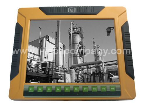
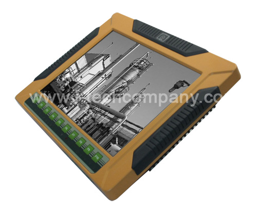
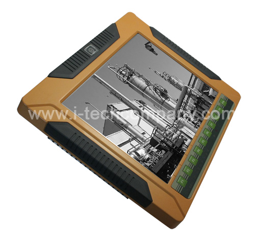
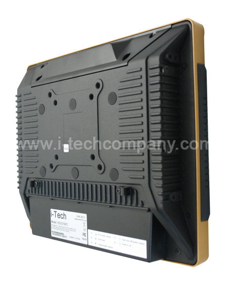
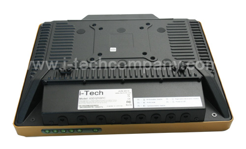
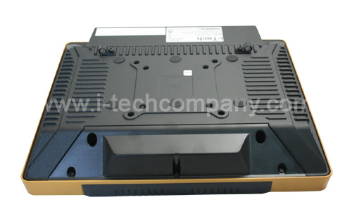
Aluminum Rugged Panel PC 12.1" 600nits XGA fanless full IP65 panel PC w/ Intel® Atom™ D525 dual core 1.8GHz (Model: IOD1210PC)
- Overview
- Download
- Fully IP 65 compliant with fanless Intel® Atom™ D525 1.8GHz dual-core processor
- 12.1'' 600 nits 1024 x 768 LCD with LED backlight
- TWIN-DC input, 9V ~ 36V and 10.5V ~ 36V, switch automatically
- Dual-band 2.4/5GHz Wi-Fi 802.11 a/b/g/n 3T3R MIMO design
- Reserved space for 3.75G / HSUPA USB module
- Optional GPS receiver
- Optional EM or Mifare RFID reader
- Optional Bluetooth module
- Built-in 1.3M pixels webcam with AF, AE and AWB capabilities
- CAN-bus interface with isolation
- F1 ~ F10 function keys which can be self-defined and user-friendly indicators
- Robust die-casting aluminum chassis
Aluminum Rugged Panel PC 12.1" 600nits XGA fanless full IP65 panel PC w/ Intel® Atom™ D525 dual core 1.8GHz (Model: IOD1210PC)
X
Inquiry/Quote Request
Features |
||||||||||||||||||||||||||||||||||||||||||||||||||||||||||||||||
Specifications |
||||||||||||||||||||||||||||||||||||||||||||||||||||||||||||||||
|
||||||||||||||||||||||||||||||||||||||||||||||||||||||||||||||||
Ordering Information |
||||||||||||||||||||||||||||||||||||||||||||||||||||||||||||||||
|
||||||||||||||||||||||||||||||||||||||||||||||||||||||||||||||||
 |
||||||||||||||||||||||||||||||||||||||||||||||||||||||||||||||||
 |
||||||||||||||||||||||||||||||||||||||||||||||||||||||||||||||||
 |
||||||||||||||||||||||||||||||||||||||||||||||||||||||||||||||||
 |
||||||||||||||||||||||||||||||||||||||||||||||||||||||||||||||||
 |
||||||||||||||||||||||||||||||||||||||||||||||||||||||||||||||||
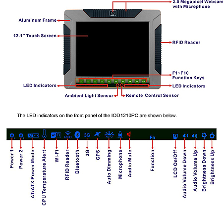
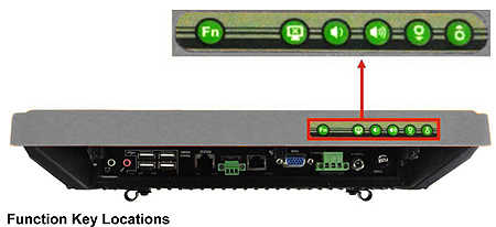
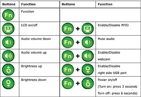
| An aluminum frame surrounds the TFT LCD Screen. The aluminum name of the IOD1210PC contains several function keys that control audio volume, LCD brightness and some other system components. | ||||||||||||||||||||||||||||||||||||||||||||||||||||||||||||||||
 |
||||||||||||||||||||||||||||||||||||||||||||||||||||||||||||||||
| The following table describes the function of these function keys. | ||||||||||||||||||||||||||||||||||||||||||||||||||||||||||||||||
 |
||||||||||||||||||||||||||||||||||||||||||||||||||||||||||||||||
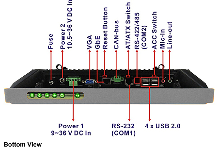
External Peripheral Device Connection |
||||||||||||||||||||||||||||||||||||||||||||||||||||||||||||||||
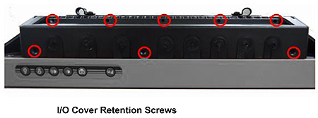
| Step 1: Remove the I/O cover by removing the eight retention screws | ||||||||||||||||||||||||||||||||||||||||||||||||||||||||||||||||
 |
||||||||||||||||||||||||||||||||||||||||||||||||||||||||||||||||
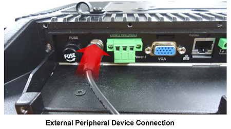
| Step 2: Connect the cable from the external peripheral device to the corresponding connector of the IOS1210PC |
||||||||||||||||||||||||||||||||||||||||||||||||||||||||||||||||
 |
||||||||||||||||||||||||||||||||||||||||||||||||||||||||||||||||
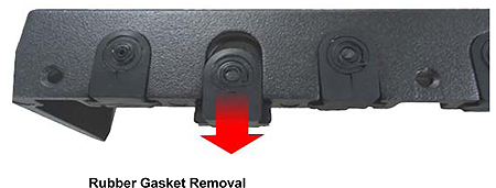
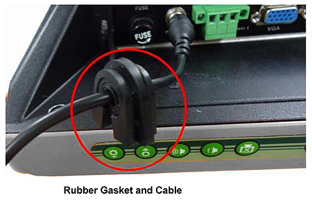
| Step 3: Take out a rubber gasket from the I/O cover | ||||||||||||||||||||||||||||||||||||||||||||||||||||||||||||||||
 |
||||||||||||||||||||||||||||||||||||||||||||||||||||||||||||||||
| Step 4: Remove some rubber rings from the gasket to make the gasket fit perfectly to the size of the cable |
||||||||||||||||||||||||||||||||||||||||||||||||||||||||||||||||
 |
||||||||||||||||||||||||||||||||||||||||||||||||||||||||||||||||
| Step 5: Repeat steps to other connected cables. | ||||||||||||||||||||||||||||||||||||||||||||||||||||||||||||||||
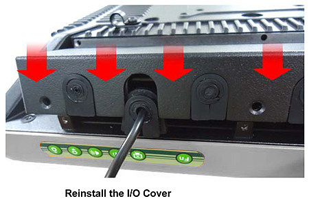
| Step 6: Install the I/O cover and make sure each rubber gasket snaps into place tightly. | ||||||||||||||||||||||||||||||||||||||||||||||||||||||||||||||||
 |
||||||||||||||||||||||||||||||||||||||||||||||||||||||||||||||||
| Step 7: Secure the I/O cover by the previously removed retention screws. |


