- Products
- Rackmount LCD Keyboard
- Rackmount LCD Monitors
- Industrial LCD Displays
- Broadcasting LCD
- Kiosks
- Open Frame Touch Monitors
- Chassis/Wall Mount LCD
- Panel Mount LCD
- Flush Mount LCD
- LCD Stainless Steel Monitor
- NEMA 4X (IP65) Displays PC
- NEMA 4X (IP65/IP66) Displays
- NEMA 6X (IP67) Displays
- SunLight Readable LCD
- All-Weather Outdoor LCD
- Panel PC (5.6"-43")
- All in One PC
- Touch Screen Display
- Rugged Industrial LCD/PC
- Digital Signage LCD
- LED Signage Display
- Military Rugged LCD
- Marine Rugged LCD
- Tablet Rugged PC
- Medical LCD Display
- Medical Panel PC
- Industrial Embedded Computer
- LCD Wall/Ceiling Mounts
- Micro Environment Monitoring System
- Industries
- Support
- Knowledge Base
- Technical Support
- Sales
- Frequently Asked Questions (FAQ)
- Video Gallery
- iTech Products Article
- Product Catalog
- Quick Download
- AUO Panel
- AVP Rackmount Series
- BCH and BCPC Series
- BHK Series
- BMPC Drivers
- CCH/CCPC/COP/CPM Series
- DigiView/ DKP series
- DCH/DVM/DCP Series Guides
- DHK series
- DMM Series
- DOD Series
- EIRMT IR touch Drivers
- ELD
- E series Intel Industrial Motherboard Mini-ITX
- EOP/ECH/EPM Series
- FD Series
- GOP/GCH/GSK Series
- KPC/KSP/KCH Series
- Netview Accessories
- Nmil Series
- OE Series
- PNPC Series
- QPC Series
- SCH series
- Touchscreen System
- VCPC/VDPC/VMPC/VPC Series
- WRD/WPM/WMRM Series
- YCH/YPM/YOP series
- Contact Us
- Inquiry
- News
- About Us
- Testimonial
2.3 Mega-Pixel 24.1" color display with DICOM calibration function. (Model: CCL240)
2.3 Mega-Pixel 24.1" color display with DICOM calibration function. (Model: CCL240)
X
Inquiry/Quote Request
- Overview
- Download
24.1" wide-screen color LCD with DICOM calibration function
High luminance, high contrast, and wide viewing angle provided by the IPS panel Stable luminance for a long period of time with a unique built-in luminance stabilizing circuit.
 Color calibration function to reproduce colors faithful to the original and grayscale compliant with DICOM Part 14
By calibrating color temperature, luminance, and gamma characteristics, reproduction of colors faithful to the original and smooth display of grayscale are possible.
Calibration function to accurately adjust gamma, color temperature, and luminance
Medical image displays are commonly required to display grayscale according to the Grayscale Standard Display Function (GSDF) defined by DICOM Part 14. The calibration function creates the optimum conditions for a medical imaging display by adjusting luminance levels, color temperature, and grayscale characteristics to achieve DICOM GSDF compliant grayscale output.
Models supported: All ME/CCL Series models, except ME183L and CCL192 plus
Note: Calibration requires an optional calibration kit*
How it works
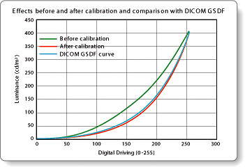
The calibration function corrects the driving level of the LUT (Look-up Table), a memory that specifies the LCD driving, and writes it in the LUT. In other words, calibration adjusts grayscale characteristics, color temperature (color displays only), and luminance.
The luminance for each driving level is corrected such that the resulting curve matches the DICOM GSDF achieving smooth grayscale output.

Graph is for explanatory purpose only.
 Automatically corrects and luminance fluctuation due to startup drift, temperature change, and aging to provide stable luminance.
Luminance stabilizing system to provides continuous stable display for medical images
 Luminance stabilizing system λ-Sentinel II


 Built-in 10bit LUT (Look-up Table) to reproduce beautiful grayscale
The built-in LUT selects the most appropriate 256 shades of gray (8bit) out of 1021 shades (10bit) to realize finer and smoother grayscale..
Built-in LUT (Look-up Table) to reproduce beautiful grayscale and TOTOKU's technology for simultaneous display of multiple shades
General-purpose displays are capable of 256 shades of gray, but due to unevenness and grayscale discontinuity, they cannot reproduce and display the subtle shading difference required for medical image displays. TOTOKU's medical image displays display the most appropriate 256 shades (8bit) out of a maximum of 12241 shades of gray using the built-in LUT. This technology realizes much finer and smoother grayscale than possible with general-purpose displays.
Moreover, combining with a TOTOKU display customized conversion table with an integrated viewer, up to 2048 shades of gray can be provided to produce film-like images on the display.
DICOM GSDF compliant curves according to the number of simultaneously available gray shades

* Images are provided for explanatory purposes only.
Special AR coating
Totoku's new *Special AR Coating technology addresses properties of focus, noise reduction, contrast, and viewing angle achieving film-like black and accurate reproduction of images. In this paper, we describe its features and physical measurement results.
*Patent pending
 Worldwide medical safety standards
This display is certified under various medical safety standards that are much more demanding than those for general-purpose IT equipment.
High luminance, high contrast, and wide viewing angle provided by the IPS panel Stable luminance for a long period of time with a unique built-in luminance stabilizing circuit.
Features
Wide-screen display with 1920 x 1200 pixels
Provides display area large enough, especially to show multiple windows at a time for using medical image analysis software
Provides display area large enough, especially to show multiple windows at a time for using medical image analysis software
By calibrating color temperature, luminance, and gamma characteristics, reproduction of colors faithful to the original and smooth display of grayscale are possible.
Calibration function to accurately adjust gamma, color temperature, and luminance
Medical image displays are commonly required to display grayscale according to the Grayscale Standard Display Function (GSDF) defined by DICOM Part 14. The calibration function creates the optimum conditions for a medical imaging display by adjusting luminance levels, color temperature, and grayscale characteristics to achieve DICOM GSDF compliant grayscale output.
Models supported: All ME/CCL Series models, except ME183L and CCL192 plus
Note: Calibration requires an optional calibration kit*
How it works
The calibration function corrects the driving level of the LUT (Look-up Table), a memory that specifies the LCD driving, and writes it in the LUT. In other words, calibration adjusts grayscale characteristics, color temperature (color displays only), and luminance.
The luminance for each driving level is corrected such that the resulting curve matches the DICOM GSDF achieving smooth grayscale output.

Graph is for explanatory purpose only.
* Calibration kit (optional)
Package contents
|
 |
 Automatically corrects and luminance fluctuation due to startup drift, temperature change, and aging to provide stable luminance.
Luminance stabilizing system to provides continuous stable display for medical images
A change in luminance affects gamma characteristics and therefore has adverse effects on diagnostic imaging. TOTOKU'smedical image displays are equipped with a luminance stabilizing system that automatically compensates for luminance changes due to startup drift, temperature change, and aging.

λ-Sentinel II consists of a luminance sensor and a luminance control circuit. The luminance sensor attached in front of the screen constantly monitors and accurately stabilizes luminance on the screen surface by sending feedback to the control circuit.


Features
Note: λ-Sentinel II module is built into the the ME/CCL Series i model displays. Other models are equipped with λ-Sentinel (TOTOKU's conventional system).
- With luminance fluctuation caused by the LCD module taken into account, highly accurate luminance control is achieved.
- Actual luminance measurements including intermediate luminance are taken on the screen surface.
- Build-in luminance sensor provided with i2 models enables even simpler calibration without attaching the calibration sensor.
Note: λ-Sentinel II module is built into the the ME/CCL Series i model displays. Other models are equipped with λ-Sentinel (TOTOKU's conventional system).
 Built-in 10bit LUT (Look-up Table) to reproduce beautiful grayscale
 The built-in LUT selects the most appropriate 256 shades of gray (8bit) out of 1021 shades (10bit) to realize finer and smoother grayscale..
Built-in LUT (Look-up Table) to reproduce beautiful grayscale and TOTOKU's technology for simultaneous display of multiple shades
General-purpose displays are capable of 256 shades of gray, but due to unevenness and grayscale discontinuity, they cannot reproduce and display the subtle shading difference required for medical image displays. TOTOKU's medical image displays display the most appropriate 256 shades (8bit) out of a maximum of 12241 shades of gray using the built-in LUT. This technology realizes much finer and smoother grayscale than possible with general-purpose displays.
Moreover, combining with a TOTOKU display customized conversion table with an integrated viewer, up to 2048 shades of gray can be provided to produce film-like images on the display.
DICOM GSDF compliant curves according to the number of simultaneously available gray shades

* Images are provided for explanatory purposes only.
High image quality provided by the IPS panel
The IPS panel is effective in preventing color and contrast changes caused by different viewing angles.
The IPS panel is effective in preventing color and contrast changes caused by different viewing angles.
Special AR coating
Totoku's new *Special AR Coating technology addresses properties of focus, noise reduction, contrast, and viewing angle achieving film-like black and accurate reproduction of images. In this paper, we describe its features and physical measurement results.
*Patent pending
Conventional LCD surface treatment
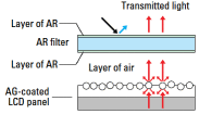
To reduce background appearances on the screen by reflection, the surface of medical displays is generally Anti- Glare (AG) coated. However, the AG coating causes focus loss due to diffused reflection and increased noise because of the diffused light that overlaps with the displayed images. For this reason, some displays used in diagnostic imaging require such finite depiction, that radiologists prefer a non- AG coated display, sacrificing reflective benefits, but gaining a crisper image. Proper focus and noise properties conflict with reduction of specular reflection, and a development of an LCD surface treatment that meets the both demand was desired. |
||||||||||||||||||||||||||||||||||||||||||||||||||||||||
|
||||||||||||||||||||||||||||||||||||||||||||||||||||||||
Special AR Coating The special Anti-Reflection (AR) coating is a surfacetreatment that provides AR layers directly on a LCD panel as shown in Table 1. Fig. 1 shows comparison of micro bright points displayed on the special AR-coated LCD and the AG-coated LCD. Due to the reduced diffused reflection by the special AR coating, the bright point is displayed more clearly with the improved focus and contrast compared to the one on the AG-coated LCD. |
||||||||||||||||||||||||||||||||||||||||||||||||||||||||
 Fig.1 Illustration of the displayed micro bright points |
||||||||||||||||||||||||||||||||||||||||||||||||||||||||
Physical measurement results of the display properties Table 2 shows physical measurement results of the display properties. The special AR-coating obtained the best results in the three surface treatments for all the measurement items except for the specular reflection (Rs). |
||||||||||||||||||||||||||||||||||||||||||||||||||||||||
Table2 Measurement results in each surface treatment
|
||||||||||||||||||||||||||||||||||||||||||||||||||||||||
| Specular reflection characteristics Fig. 4 shows photographs of each LCD with 4 different surface treatments reflecting the background in the lighted room. Fig. 5 shows image analysis of the photographs in Fig. 4. The X-axis represents the horizontal direction in the photographs and the Y-axis represents relative luminance. A piece of white paper was placed in front of the surface of each LCD panel to take a photo of its appearance on the screen by reflection. Although the paper edge appears more clearly on the special AR-coated LCD than the AG-coated LCD or the AG-coated LCD with the AR filter, as shown in Fig. 5, relative luminance of the special AR-coated LCD is lowest. Conversely, the white paper appears most clearly on the mirror-shiny surface of the *Glare type LCD, and its relative luminance is the highest of all LCDs. *Non-AG-coated LCD panel to improve the noise and the focus properties. |
||||||||||||||||||||||||||||||||||||||||||||||||||||||||
 Fig.4 Comparison of the background reflected on the screen in the lighted room |
 Fig. 5 Graph of the photograph analysis |
|||||||||||||||||||||||||||||||||||||||||||||||||||||||
The special AR-coating obtained the best results in the three surface treatments for all the testing items except for the specular reflection (Rs). Although the reflection coefficient in the specular reflection is slightly lower than the others, as shown in Fig. , the special AR-coated LCD achieves the lowest relative luminance of the reflected image. For these reasons, it was indicated that the special AR-coating is the surface treatment best suited for medical displays. |
||||||||||||||||||||||||||||||||||||||||||||||||||||||||
Picture-in-Picture
Allows you to have the second window on the screen.
Allows you to have the second window on the screen.
This display is certified under various medical safety standards that are much more demanding than those for general-purpose IT equipment.
Specifications
| Model Name | CCL240 (Without Special AR Coating) |
CCL240 /AR (With Special AR Coating) |
|
|---|---|---|---|
| LCD Panel | Technology | 24.1-inch, Color, IPS Technology | |
| Display Area | 518mm x 324mm | ||
| Pixel Pitch | 0.27mm x 0.27mm | ||
| Contrast Ratio | 1000:1 (typ) | ||
| Maximum Luminance | 400cd/m² (typ) (calibrated to 150cd/m2 and 200cd/m2, 150cd/m2 by factory default) |
||
| Viewing Angle | 178° horizontal and vertical (typ) | ||
| Visual Performance | Available Resolution | 1920 x 1200 | |
| Color Display | Full color (16.77 million colors) | ||
| Input Signal | Input Sync Signal | Digital DVI / Analog RGB | |
| Plug and Play | DDC2B compliant | ||
| Input Power Supply | Input | 100V-240V (-10%, +10%) 50/60Hz (Internal power supply) | |
| Maximum Power Consumption | 110W (typ), (with power management feature) | ||
| Features | Calibration Control | Luminance, Gamma, Color temp. (A calibration kit is required.) | |
| Standards | MET (UL60601-1), MET-C (CSA C22. 2 No 601. 1), MDD/CE, FCC-B, VCCI-B, (FDA510(k): pending) | ||
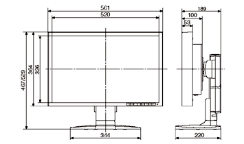
| Physical Characteristics | Dimensions (WxHxD) | 561 (W) X 467 / 529 (H) X 220 (D) mm | |
| Weight | Net: approx. 11.7kg, Without tiltstand: approx. 7.3kg | ||
| Tilt Stand | Tilt, swivel, landscape/portrait rotation | ||
| Mount | 100mm VESA compliant | ||
| Security Slot | Antitheft security slot | ||
| Accessories | 3P power cord, DVI cable, VGA cable, User manual | ||
Dimensions
 |


